

 6Likes
 LinkBack URL
 About LinkBacks
While it isnt very common, I also get the occasional shot that isnt picked up by the Labradars internal microphone. I briefly thought about buying a packaged recoil-based trigger, but then perhaps a DIY project would be more interesting, as I have some spare microelectromechanical (MEMS) capacitive accelerometers in the workshop. Combined with an oscilloscope, and aspects of a rifles operation can also then be studied, such as measuring the lock-time, or the acceleration at the end of the barrel on firing. Triggering the chronograph via an accelerometer IC is also going to be far more consistent than using one of the make-break motion detectors that are reported on some of the other forums as having been used with the Labradar. Being able to aligning the axis of response with the barrel reduces the likelihood of triggering from movement in directions other than to recoil such as when closing down the bolt handle.
For some background information, here is a link to the to the JKL site where one of the commercial options is detailed:
https://jklprecision.com/product/labradar-trigger/
Here is the Australian suppliers page for the Recoil Activation Trigger (RAT):
https://grenfellarmouringservice.com...pid=0000000235
The (claimed) original after-market inertia trigger for the Labradar is here:
https://pietrecoiltrigger.com/
The commercial units linked to above probably use integrated circuit accelerometers.
Linked here are examples of the somewhat non-directional motion sensor for a basic DIY trigger referred to above: https://www.adafruit.com/product/2384
https://sparks.gogo.co.nz/catalog/Se...8010P-943.html
The cut-away shows the inside workings a coil around a central rod that touch together with vibration. Available from Core Electronics, NSW, if you wanted to go down that path.
And here is a link to reports of folk who have used these sensors with varying degrees of success:
https://www.ozfclass.com/phpbb/viewt...hp?f=5&t=12152
https://www.ar15.com/forums/Armory/D...523956/?page=1
Here is the item Labradar would prefer was purchased; their external microphone:
https://buymylabradar.com/products/a...rigger-adapter
Folk here went to some trouble quantifying the requirements of the Labradars external trigger input which was helpful:
https://www.thehighroad.org/index.ph...er-diy.872618/
Finally here is a link to the thread where Tikka7mm08 reviewed the RAT in 2020 on this forum:
https://www.nzhuntingandshooting.co....ger-rat-66653/
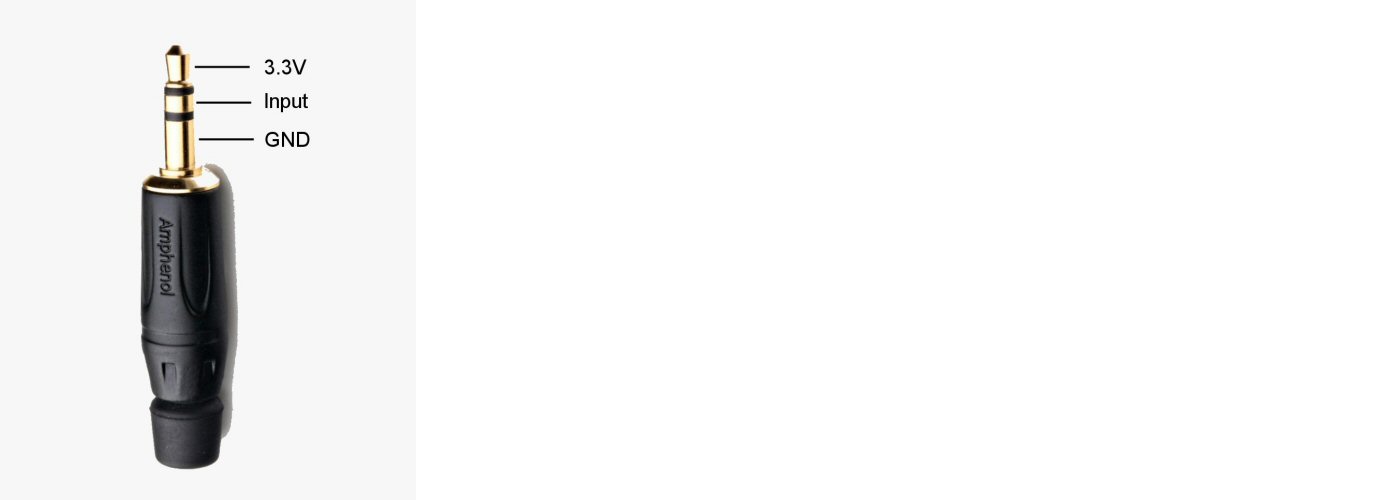
The designers of the Labradar thoughtfully provided access to a regulated 3.3 volt supply at the 3.5mm stereo socket along with the signal input. This opens up a whole range of external electronic possibilities (which no doubt all invalidate the warranty) but nevertheless I decided to keep it simple and wire up an accelerometer with just a bit of passive output conditioning.
The peak acceleration for a given rifle may be predicted using the calculator found here:
https://robrobinette.com/Gun_Recoil_...r.html#g_Force
Using this it seemed that 100350g could be expected for centrefires. I wasnt too intent anyway on trying to exactly match the full-scale capabilities of an accelerometer to the peak recoil. The current crop of MEMS capacitive accelerometer ICs are rated to withstand 2000g or more, so being attached to a rifle isnt going to harm them. All that will happen if they max out, is that the output voltage will hit the supply rail, and the resulting output pulse on firing will then progressively lengthen in duration as the acceleration increases with respect to the accelerometers sensitivity in millivolts-per-g. The Labradar here is transmitting continuously on 24.120 GHz while the orange LED is on, so triggering would appear to be the signal needed to initiate attempting to take readings, perhaps on the rising edge of the input pulse or more probably within a short time period of the preset triggering threshold having been exceeded. The exact timing of the triggering pulse is probably not particularly critical, in much the same way that neither is the exact time a bullet takes to enter the usable region of the Labradars antenna radiation pattern. I figured that accelerometers with a working range between ±15g and ±50g would do the job.
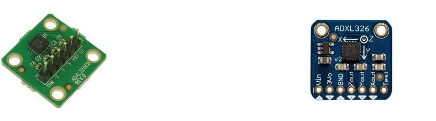
For this application as Im describing it, an analogue output from the accelerometer is required, along with the ability to run off the 3.3 volt supply from the Labradar. Stocks of accelerometer ICs are already pretty thin on the ground with the supply issues at present for active components, and since devices with analogue outputs are already in the minority over those with digital/register outputs, there isnt really much suitable from the usual component resellers at the moment. Given time they will come back into stock. A part like the ADXL326 would be a perfect candidate. With a somewhat more questionable provenance, this particular part may be source from off AliExpress. It should also be pointed out that the days of large electronic components are almost over. Being able to work with parts intended for surface mounting is now a must. The size of the ADXL326 is 4mm x 4mm. A 20mm x 20mm evaluation board is available and would be easier to work with, but is a bit expensive in my view for what it is (below left). Again there are cheaper AliExpress alternatives (right). I ended up using an older ADXL150 with a voltage-doubler to work around the need for a 5V supply with that particular part.
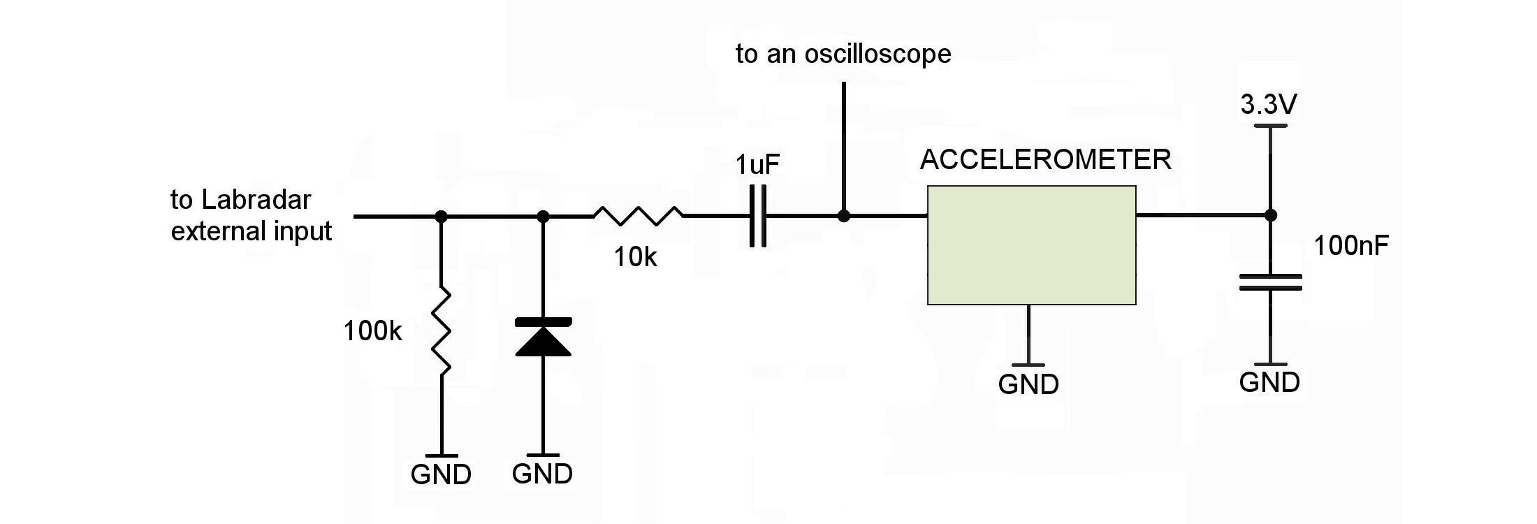
Analogue accelerometers have ratiometric outputs, and since they measure acceleration in both directions, an at-rest zero-g condition will put the output pin at half the supply. This wont be suitable for interfacing with the Labradar directly, as it would interpret the constant 1.65V as a triggering condition, so the DC component needs to be blocked off with a capacitor. I also added a series resistor and diode to protect the Labradar input by clamping the negative-going waveforms. The outputs for the other axes from the accelerometer could have the same output circuitry if they are going to be used or just left not connected. Here is a suitable circuit:
Something with a low forward voltage (like a BAT64 or similar) is suitable for the diode. The values of the other components can be played with for the desired result. Connecting the oscilloscope directly to the accelerometer output better allows for measurement readings that represent forces acting in both directions down the axis of the barrel to be observed, albeit still with some compression of the negative response due to the diode clamping in combination with the device output impedance. The PCB may be glued down to a piece of acrylic plastic that acts as a light-weight backing plate, which in turn can be fastened to the rifle being tested by whatever detachable means is convenient.
This is what was observed on dry firing and where the accelerometer was orientated to the rifle so that an acceleration in the direction of recoil down the length of the rifle would result in a positive voltage. The vertical gradations each represent 2.5 millisecond of elapsed time, left to right.
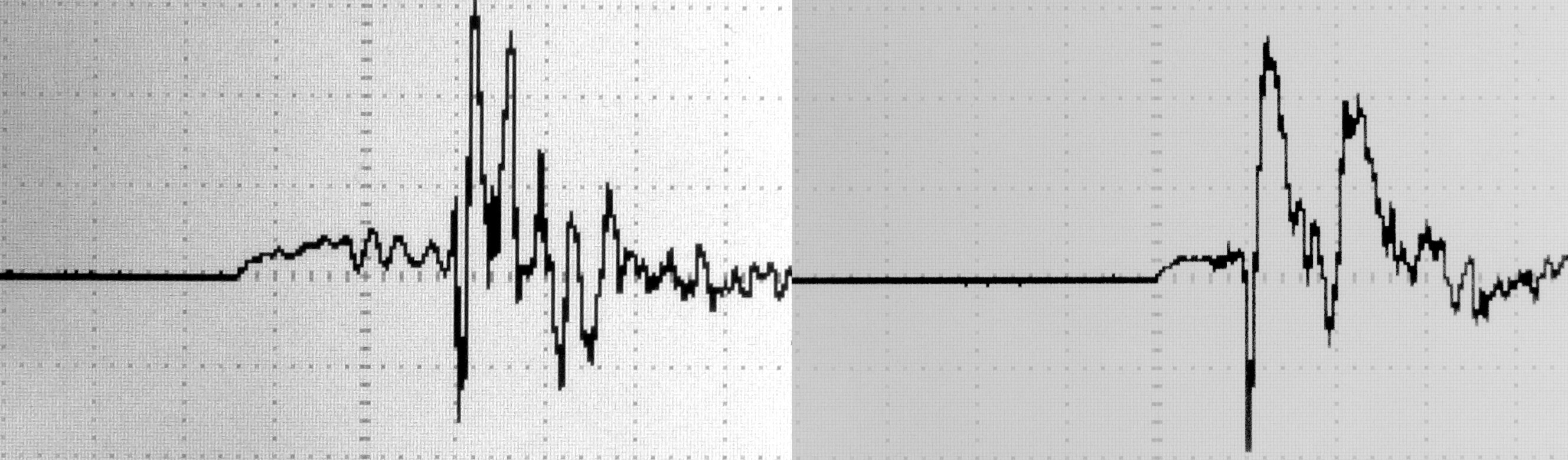
On the left is the response from a vz. 33 Mauser action. The initial rearward acceleration of the whole rifle is in response to the fall of the firing rod and cocking-piece. This is followed by a series of sharper vibrations when the rod impacts the bolts interior stop. The lock-time may then be read off the trace as around 7.5msec; reasonably snappy for a Mauser from what I have read. The variation during the second half of the lock-time may be due to mechanical resonances or perhaps portions of the striker spring contacting the cast interior bolt wall. On the right is a trace from a Barnard P action; a cleaner and more uniform response on firing, and the lock-time is 2.4msec. The rifle is over twice the weight of the Mauser so the resulting acceleration amplitudes are not directly comparable.
I havent mentioned the amplitude of the signals, as this very much depends on both the sensitivity of the accelerometer chosen and the components placed at the output. Conveniently accelerometers may be calibrated using gravity by tipping them on their sides from the horizontal, first in one direction, and then flipping them 180°, noting the change in output voltage in response to the change between +1g to 1g. Dividing by two then gives the volts-per-g response. Having calibrated my setup I then measured the response for slamming the bolt shut as hard as I could on an empty chamber which peaked at 12g. This is why I recommended and used an accelerometer in the sensitivity range of ±15g to ±50g or so. It should then be fairly straightforward to select a combination of the output resistive divider and the triggering sensitivity from the Labradars set-up menu to reliably trigger from the >100g when firing while remaining unresponsive to other manipulations of the rifle.
Inertia triggering does allow for more flexibility with the positioning of the chronograph. However since the Labradar can only ever calculate bullet distances from itself, and estimate all velocities as if the bullet had originated from the chronograph, it would on the face of it then still appear best to keep it as close to the rifles muzzle as possible and keep the offset setting at 15cm.
Welcome guest, is this your first visit? Create Account now to join.
Welcome to the NZ Hunting and Shooting Forums.
Search Forums


User Tag List
+ Reply to Thread
Results 1 to 3 of 3
-
28-09-2022, 07:47 PM #1Member


- Join Date
- May 2012
- Location
- Porirua
- Posts
- 974
Triggering the Labradar with an Accelerometer
-
-
28-09-2022, 08:37 PM #2Member
- Join Date
- Mar 2016
- Location
- Waikato
- Posts
- 403
Thanks for taking the time to write that up. I use a remote mic to trigger mine and a mate uses an accelerometer probably one of the commercial ones you mentioned. There is a bit of info on the labradar Facebook group about diy accelerometers which I haven’t had time to go through yet, doubt it will be as comprehensive as yours. Very interesting how you measured and compared lock time. One of the things I really like about this forum is occasionally there is a really informative post, to me at least, cheers.
Beaker likes this.
-
29-09-2022, 09:01 AM #3Member
- Join Date
- Feb 2014
- Location
- Hawkes Bay
- Posts
- 2,420
The JLK works fine but as with ?any accelerometer triggering, a non-shot impulse like hard working the bolt can trigger a measurement. Easy to delete though with one button press.


 Reply With Quote
Similar Threads
-
Labradar Down
By sneeze in forum Reloading and BallisticsReplies: 27Last Post: 21-11-2018, 12:49 PM -
Labradar (Where to buy)
By outdoorlad in forum Reloading and BallisticsReplies: 22Last Post: 15-10-2018, 01:46 PM
Tags for this Thread
 Posting Permissions
- You may not post new threads
- You may not post replies
- You may not post attachments
- You may not edit your posts
Welcome to NZ Hunting and Shooting Forums! We see you're new here, or arn't logged in. Create an account, and Login for full access including our FREE BUY and SELL section Register NOW!!
All times are GMT +13. The time now is 04:58 AM.

Bookmarks